
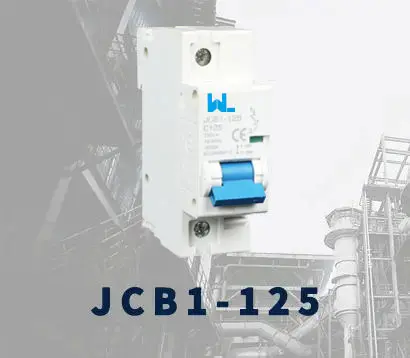
 JCB1-125
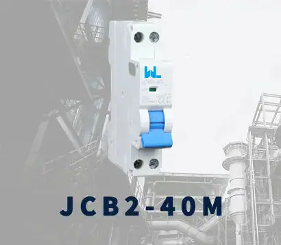 JCB2-40M
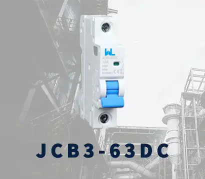 JCB3-63DC
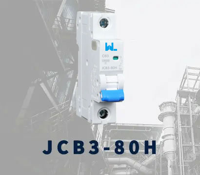 JCB3-80H
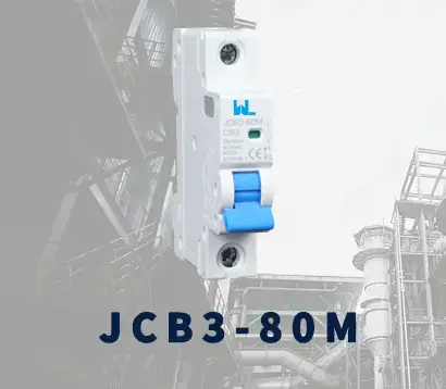 JCB3-80M
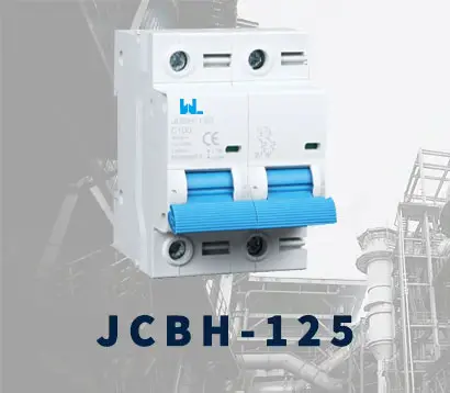 JCBH-125
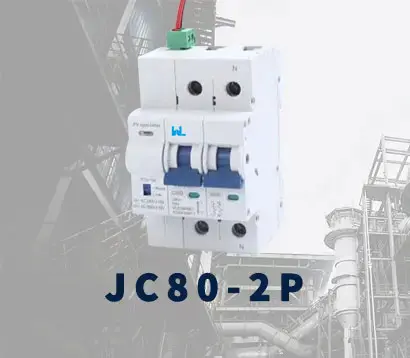 JC80-2P
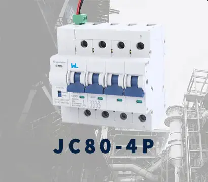 JC80-4P
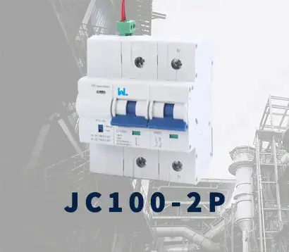 JC125-2P
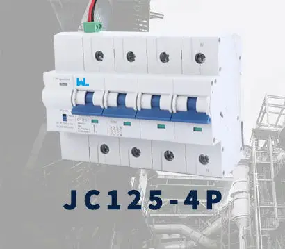 JC125-4P
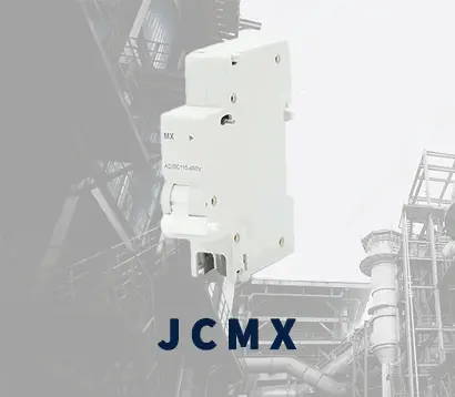 JCMX
JCMX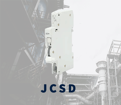 JCSD
JCSD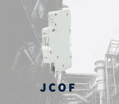 JCOF
JCOF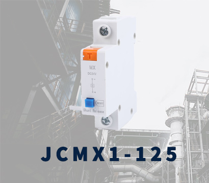 JCMX1-125
 JCOF1-125
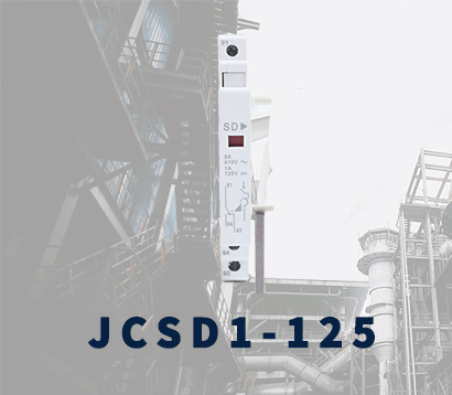 JCSD1-125
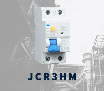 JCR3HM
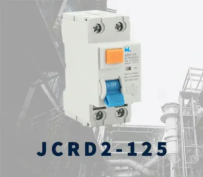 JCRD2-125
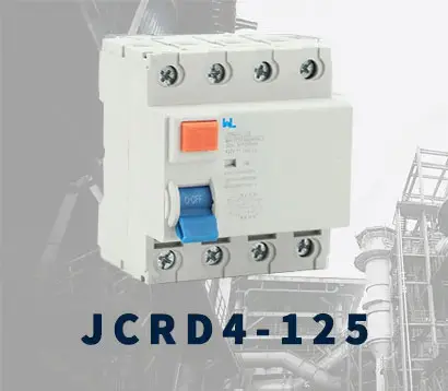 JCRD4-125
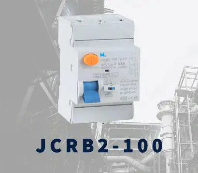 JCRB2-100
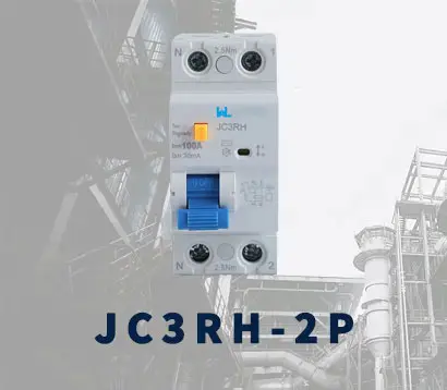 JC3RH-2P
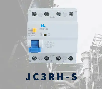 JC3RH-S
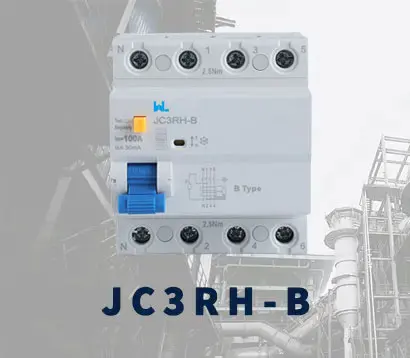 JC3RH-B
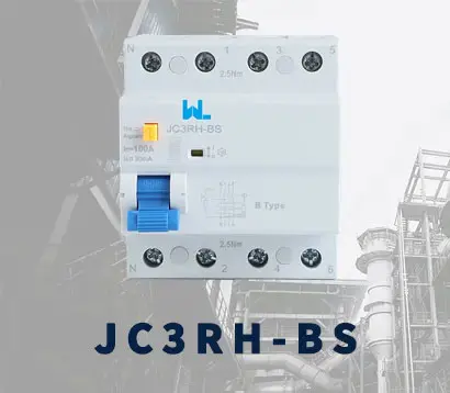 JC3RH-BS
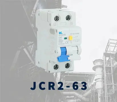 JCR2-63
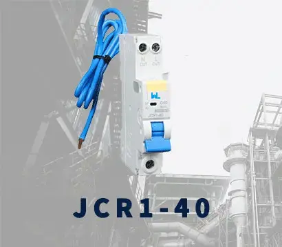 JCR1-40
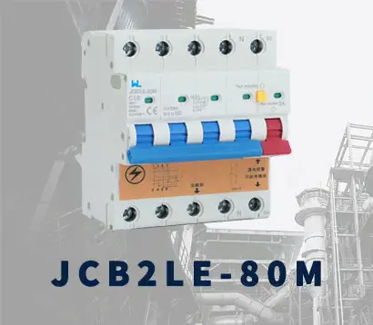 JCB2LE-80M
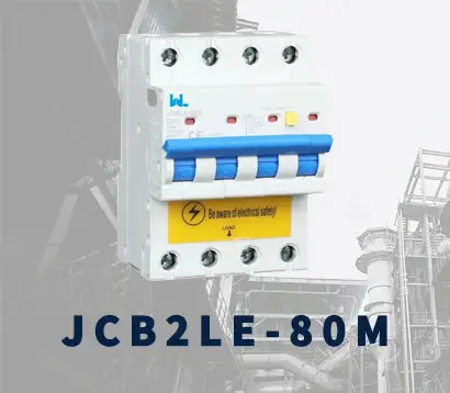 JCB2LE-80M
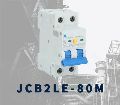 JCB2LE-80M
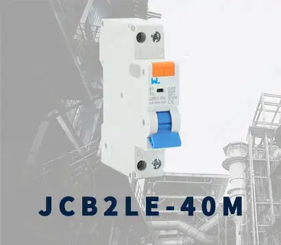 JCB2LE-40M
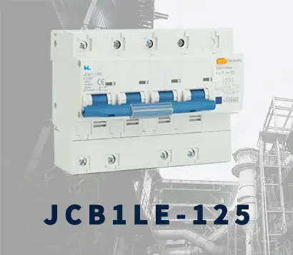 JCB1LE-125
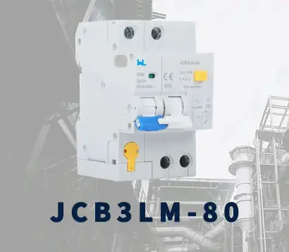 JCB3LM-80
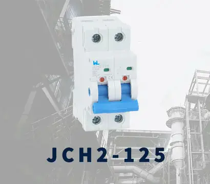 JCH2-125
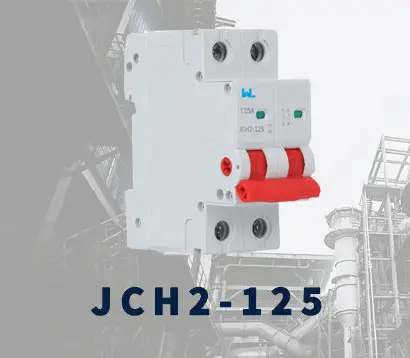 JCH2-125
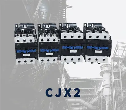 CJX2
CJX2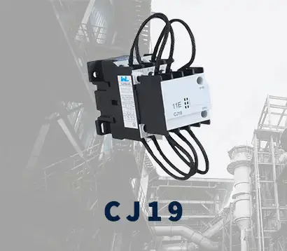 CJ19
CJ19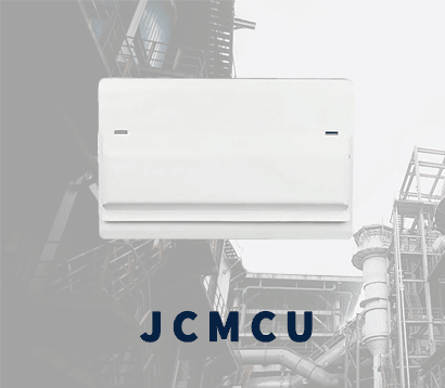 JCMCU
JCMCU JCHA
JCHA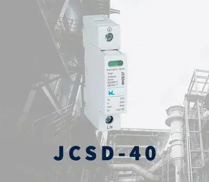 JCSD-40
 JCSD-60
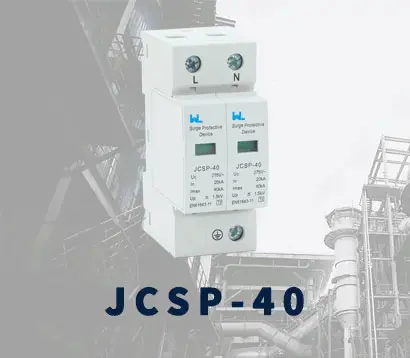 JCSP-40
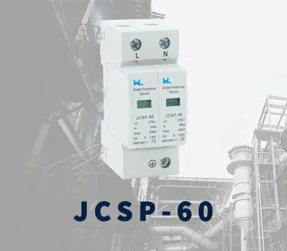 JCSP-60
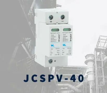 JCSPV
JCSPV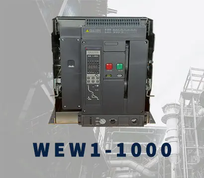 WEW1-1000
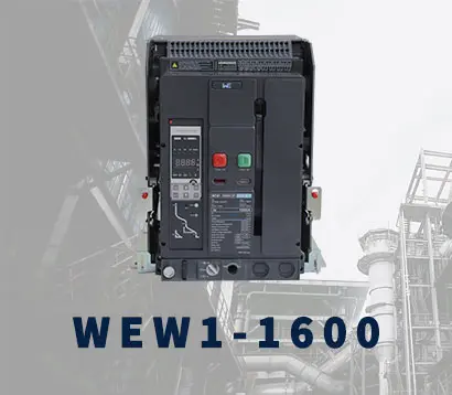 WEW1-1600
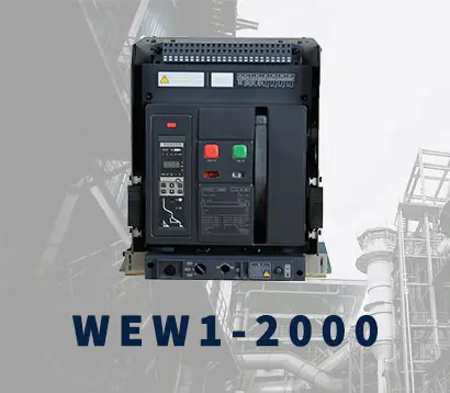 WEW1-2000
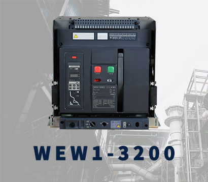 WEW1-3200
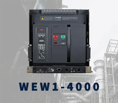 WEW1-4000
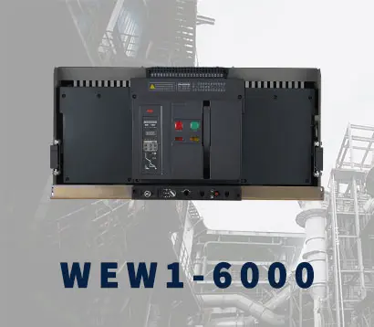 WEW1-6300
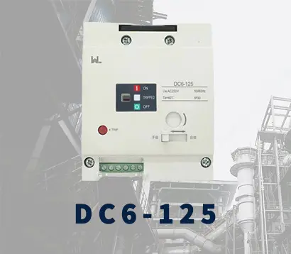 DC6-125
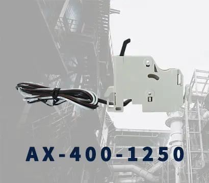 AX-400-1250
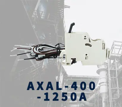 AXAL-400-1250A
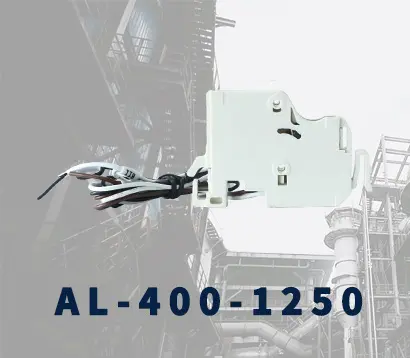 AL-400-1250
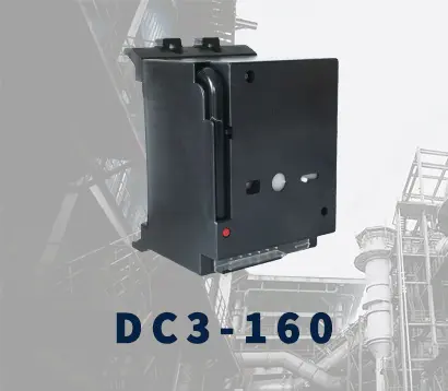 DC3-160
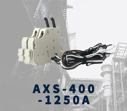 AXS-400-1250A
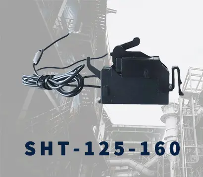 SHT-125-160
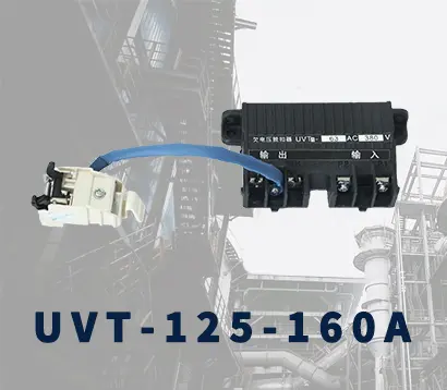 UVT-125-160A
 P-250A-3P-A
 400-3P/4P terminal cover
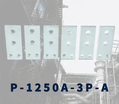 1250-3Pmccb accessories busbar
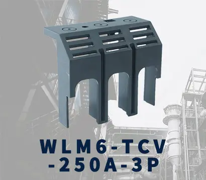 250-3P terminal conver
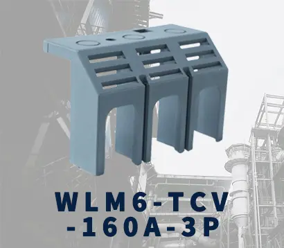 WLM6-TCV-160A-3P
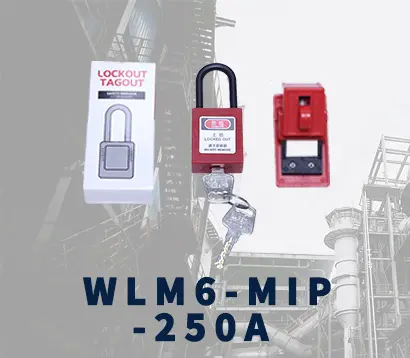 WLM6-MIP-250A
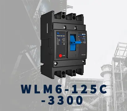 WLM6-125A-3300 3P/4P
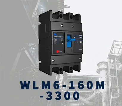 WLM6-160A-3300 3P/4P
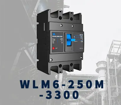 WLM6-250A-3300 3P/4P
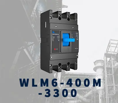 WLM6-400A-3300 3P/4P
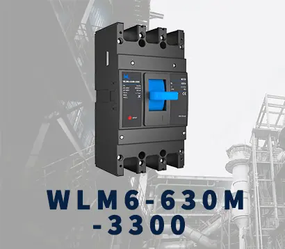 WLM6-630A-3300 3P/4P
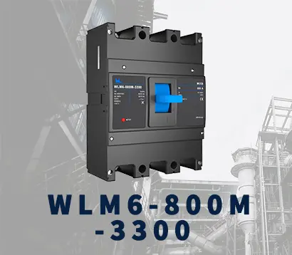 WLM6-800A-3300 3P/4P
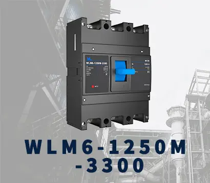 WLM6-1250A-3300 3P/4P
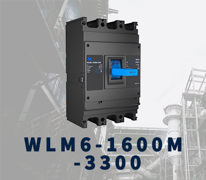 WLM6-1600A-3300 3P/4P
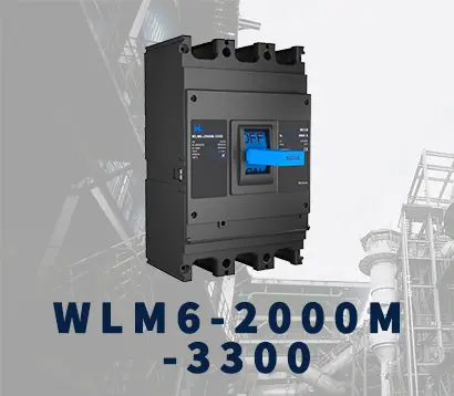 WLM6-2000A 3P/4P
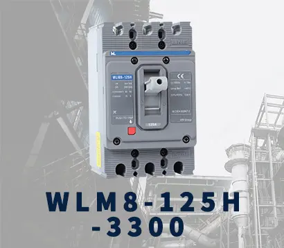 WLM8-125H-3300
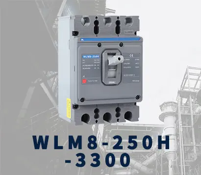 WLM8-250H-3300
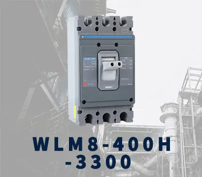 WLM8-400H-3300
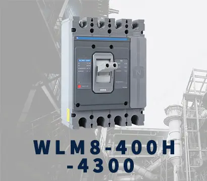 WLM8-400H-4300
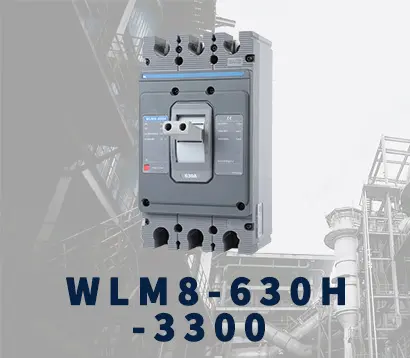 WLM8-630H-3300
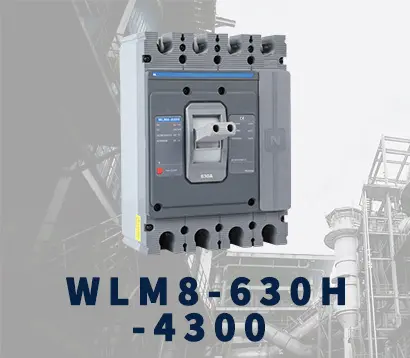 WLM8-630H-4300
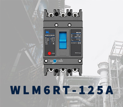 WLM6RT-125A
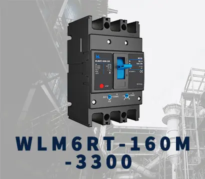 WLM6RT-160A
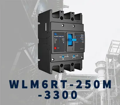 WLM6RT-250A
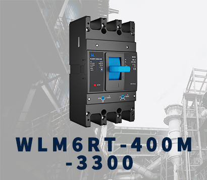 WLM6RT-400A
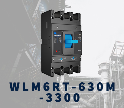 WLM6RT-630A
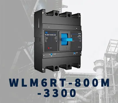 WLM6RT-800A
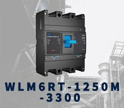 WLM6RT-1250A
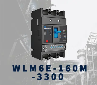 WLM6E-160A-3300 3P
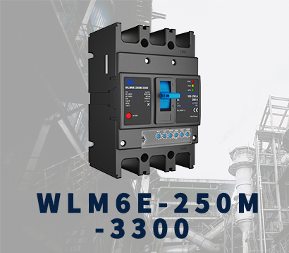 WLM6E-250A-3300
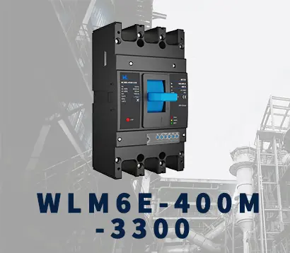 WLM6E-400A-3300 3P/4P
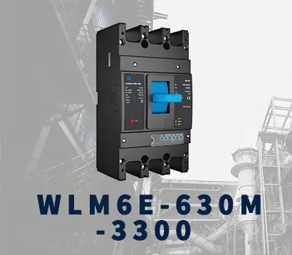 WLM6E-630A-3300
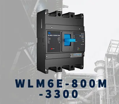 WLM6E-800A-3300 3P/4P
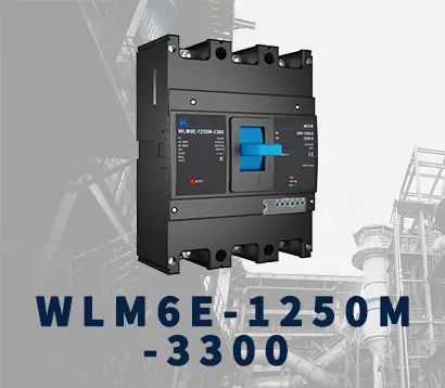 WLM6E-1250A-3300
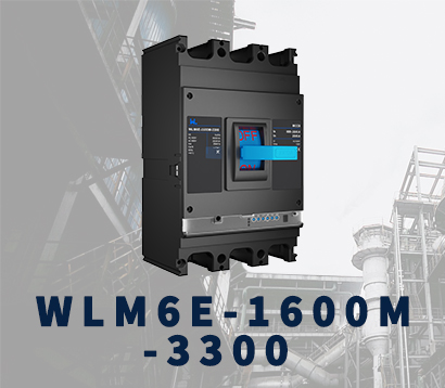 WLM6E-1600-3300 3P/4P
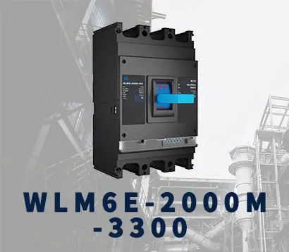 WLM6E-2000A-3300 3P/4P
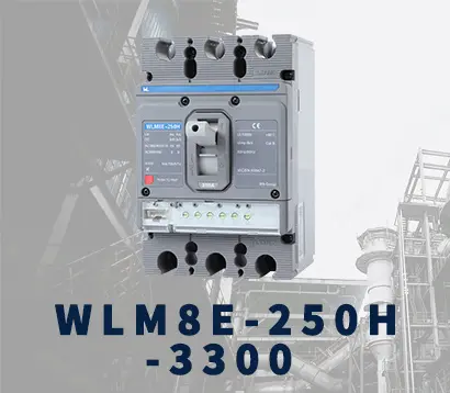 WLM8E-250H-3300
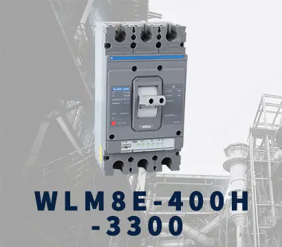 WLM8E-400H-3300
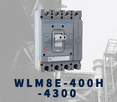 WLM8E-400H-4300
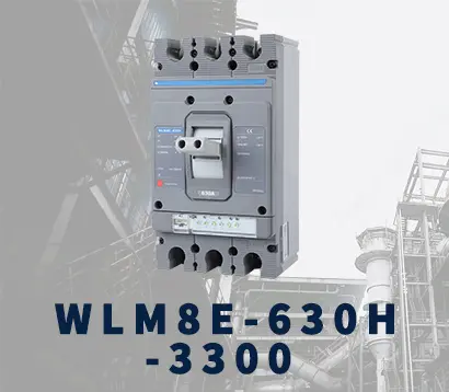 WLM8E-630H-3300
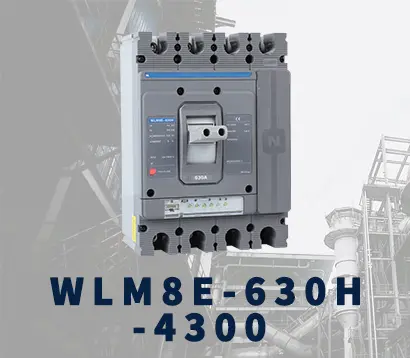 WLM8E-630H-4300
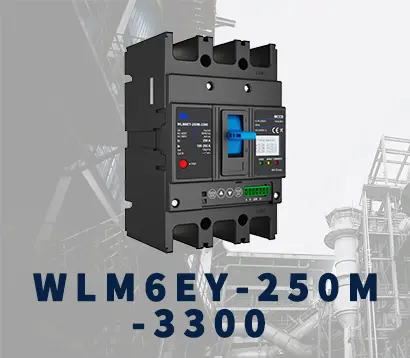 WLM6EY-250-3300 3P/4P
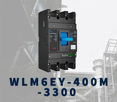 WLM6EY-400 3P/4P
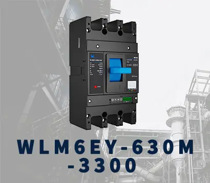 WLM6EY-630 3P/4P
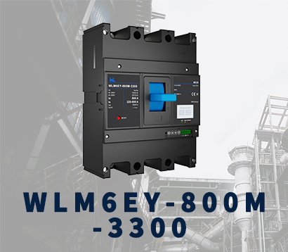 WLM6EY-800A 3P/4P
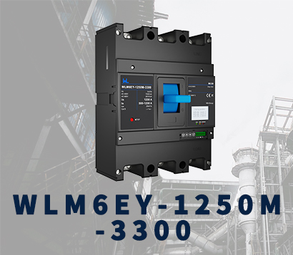 WLM6EY-1250A 3P/4P
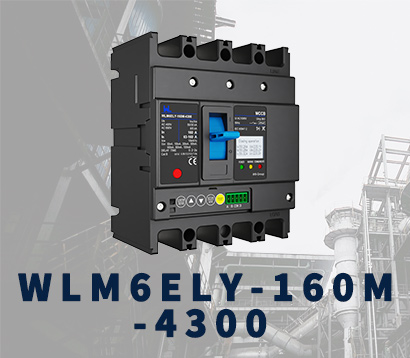 WLM6ELY-160A
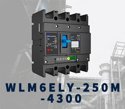 WLM6ELY-250A
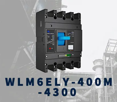 WLM6ELY-400A
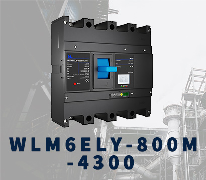 WLM6ELY-800A
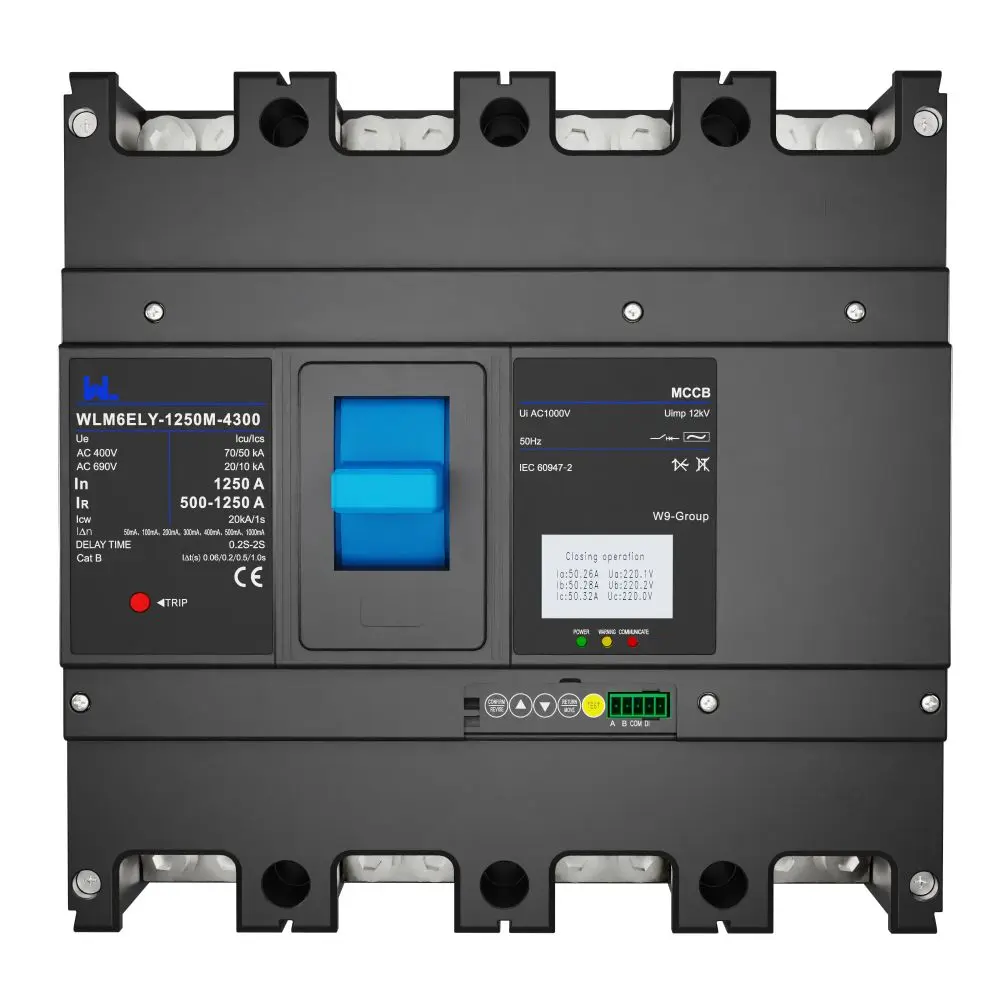 WLM6ELY-1250A
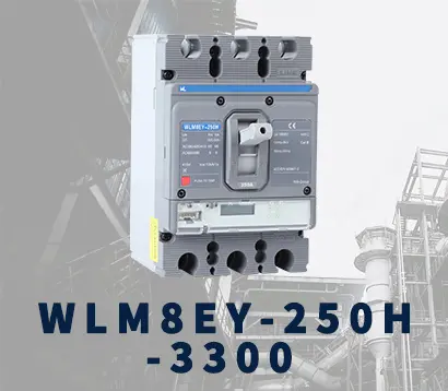 WLM8EY-250H-3300
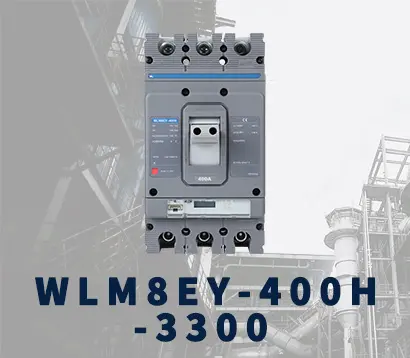 WLM8EY-400H-3300
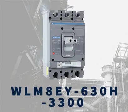 WLM8EY-630H-3300
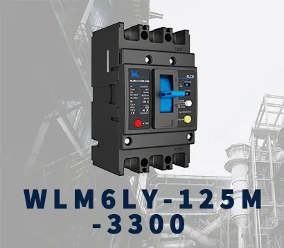 WLM6LY-125A
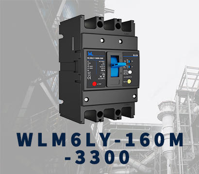 WLM6L-160A
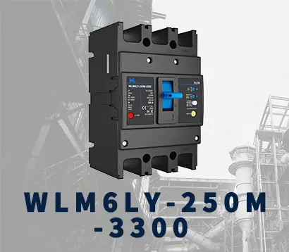 WLM6LY-250A
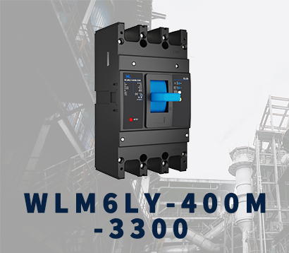 WLM6LY-400A
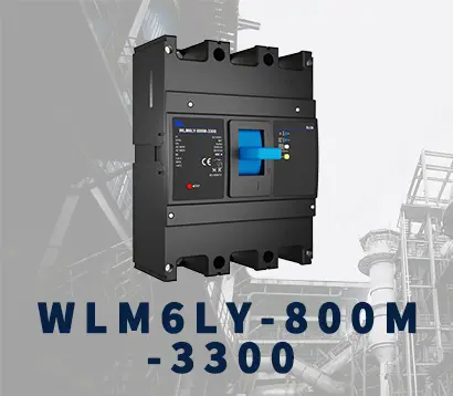 WLM6LY-800A
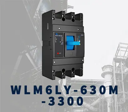 WLM6LY-630A
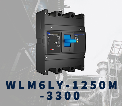 WLM6LY-1250A
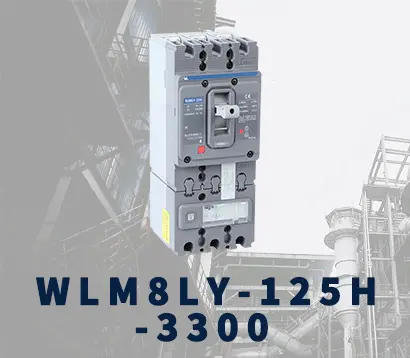 WLM8LY-125H-3300
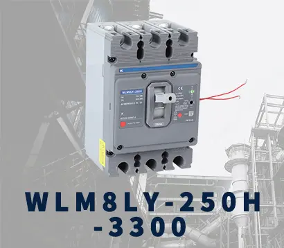 WLM8LY-250H-3300
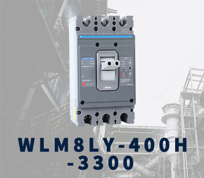 WLM8LY-400H-3300
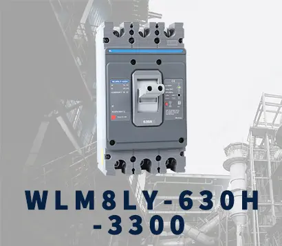 WLM8LY-630H-3300
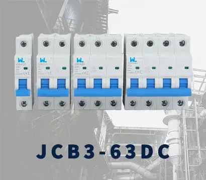 JCB3-63DC
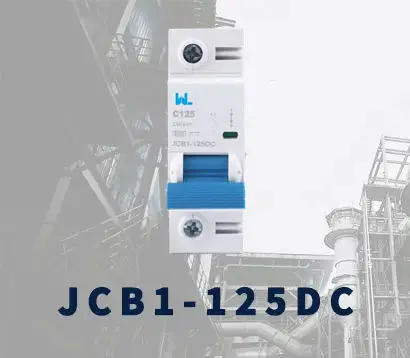 JCB1-125DC
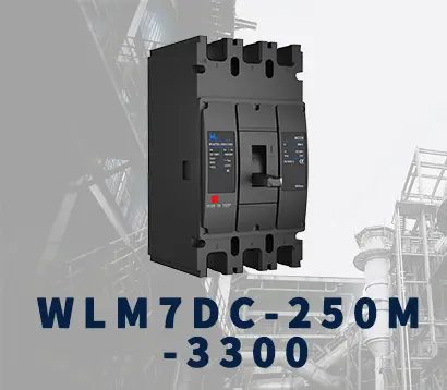 WLM7DC-250A-2300 2P/3P
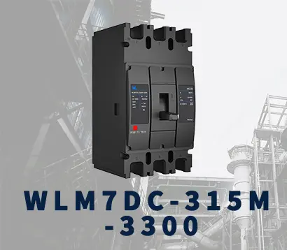 WLM7DC-315A-3300 2P/3P
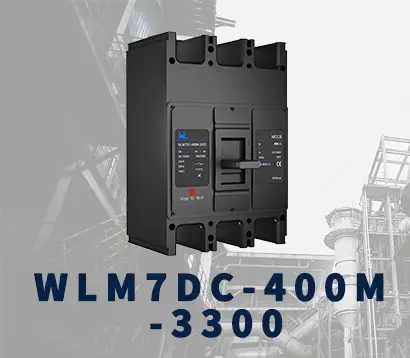 WLM7DC-400A-2300 2P/3P
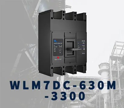 WLM7DC-630A-3300 3P
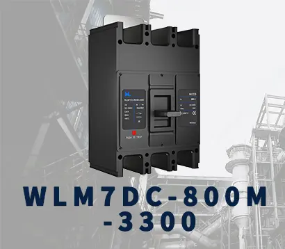 WLM7DC-800A-2300 2P/3P
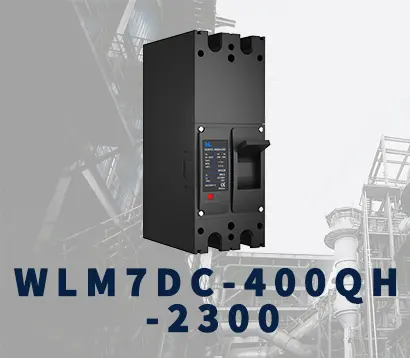 WLM7DC-400A 2300
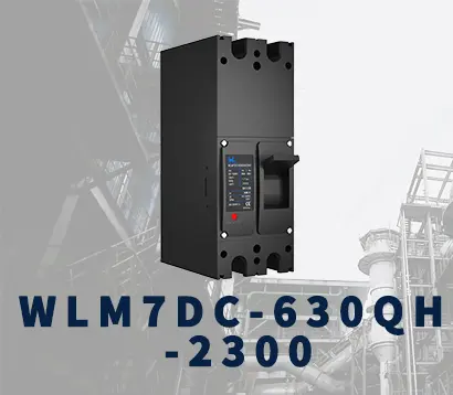 WLM7DC-630A-2300 2P
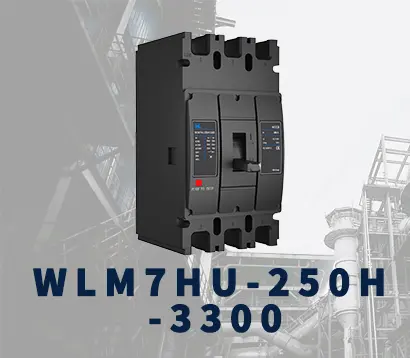 WLM7HU-250-3300 3P
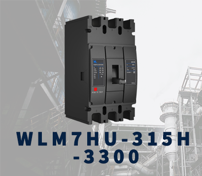 WLM7HU-315-3300 3P
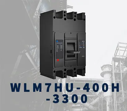 WLM7HU-400-3300 3P
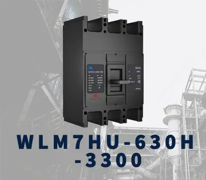 WLM7HU-630-3300 3P
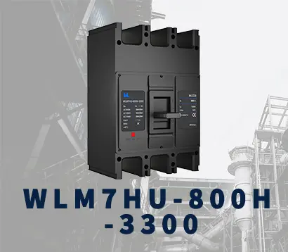 WLM7HU-800-3300 3P
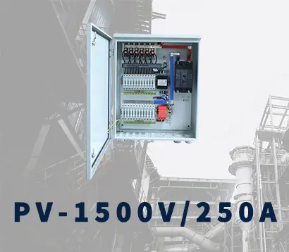 PV-1500V/250A
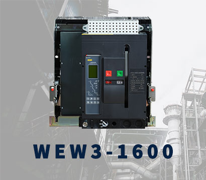 WEW3-1600
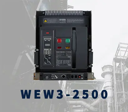 WEW3-2500
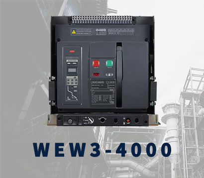 WEW3-4000
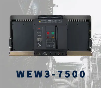 WEW3-7500





Why Choose Adjustable MCCB for Global Electrical Projects?
Modern electrical projects rarely share the same load profile, fault level, or installation environment. A distribution board in Singapore may face different operating conditions than one in Germany, Brazil, or Kenya. This is where Mccb Adjustable technology becomes valuable. Its adjustable long-time, short-time, and instantaneous settings help engineers coordinate protection with actual system requirements. The result can be better selectivity, reduced nuisance tripping, and more dependable equipment protection.
No setting fits every project. Dr. John J. Shea, a recognized power-system protection engineer, expresses the principle clearly: “Protection works only when settings match the system they serve.” That idea supports the growing use of Mccb Adjustable devices in global electrical applications. Engineers can account for cable size, transformer capacity, motor starting current, ambient temperature, and expected fault current. A properly adjusted breaker can remain closed during a normal motor start, then trip quickly during a serious fault. That difference matters on a busy factory floor.
Field experience also reveals an uncomfortable truth. Adjustable protection does not remove engineering responsibility. Incorrect settings can create hidden risks. A breaker may appear advanced while remaining poorly coordinated. Project teams should verify calculations, test trip behavior, document final settings, and review changes after expansion. Manufacturer instructions and local standards still matter. So does practical judgment. Mccb Adjustable is not a shortcut. It is a flexible protection tool that rewards careful design, trained commissioning, and honest review. Global projects need that balance. They need technology, but they also need people willing to question the first answer.

What Is an Adjustable MCCB?
An adjustable molded-case circuit breaker (MCCB) protects low-voltage circuits from overloads and short circuits. Unlike a fixed-trip breaker, it lets technicians set the operating current within a defined range. This flexibility matters when load conditions change. A motor feeder, for example, may draw 160 A during normal operation but need different protection after expansion. The adjustment does not increase the breaker’s interrupting capacity. That detail is easy to miss.
Inside, thermal-magnetic or electronic trip units monitor current and respond to abnormal conditions. Depending on design, users can adjust long-time, short-time, and instantaneous pickup values. A qualified engineer compares these settings with cable ampacity, transformer data, motor starting current, and downstream protection. Poor coordination causes trouble. It may trip an upstream breaker first, disconnecting a larger area. Field commissioning often reveals settings copied from another site. Those settings may ignore local heat, cable grouping, or actual starting currents. Settings should be recorded on a panel schedule and verified by injection testing when project procedures require it.
For global projects, adjustable MCCBs can support varied loads with fewer enclosure variations. Not a universal fix. Voltage, frequency, ambient temperature, installation method, and local standards still affect selection. An incorrect setting can weaken protection or create nuisance trips. Engineers should review technical data and applicable standards before energizing the circuit. They may also lock or seal settings where unauthorized changes are possible. One uncomfortable question remains: does the chosen range fit the real load, or only the estimate? That answer may change after commissioning.
| Data Dimension | Typical Adjustable MCCB Data | Why It Matters in Global Projects |
|---|---|---|
| Definition | A molded-case circuit breaker with a trip unit whose protection settings can be adjusted within a specified range. | Allows one breaker design to be coordinated with different loads, cable sizes, and operating conditions. |
| Rated Current Range | Common MCCB frame sizes cover approximately 16 A to 1,600 A; larger ratings are available in some product families. | Supports applications ranging from small distribution boards to industrial feeders and large building services. |
| Long-Time Overload Adjustment | Electronic trip units commonly provide an adjustable long-time pickup, often around 0.4 to 1.0 times the trip-unit rating, depending on the design. | Helps match the breaker to the continuous ampacity of conductors and the expected operating load. |
| Short-Time Pickup Adjustment | Many electronic trip units allow short-time pickup and delay settings to be configured for selective coordination. | Can help downstream breakers clear faults first while upstream equipment remains energized when safely possible. |
| Instantaneous Trip Adjustment | Electronic units may offer adjustable instantaneous pickup; the available range varies by frame size and trip-unit design. | Useful for managing high prospective fault currents and coordinating protection in systems with different source conditions. |
| Short-Circuit Breaking Capacity | Typical MCCB interrupting ratings range from about 18 kA to more than 100 kA, depending on voltage, construction, and test standard. | The selected interrupting rating must be equal to or greater than the available fault current at the installation point. |
| Rated Operational Voltage | Common systems operate at 230/400 V or 277/480 V AC; many MCCBs are designed for systems up to 690 V AC, while some are rated higher. | Voltage compatibility supports use across common IEC and other international distribution systems. |
| Number of Poles | Available configurations commonly include 2-pole, 3-pole, and 4-pole versions. | Makes it possible to protect single-phase, three-phase, and systems requiring neutral switching. |
| Trip Unit Type | Options typically include thermal-magnetic trip units and electronic trip units with adjustable protection functions. | Project engineers can select basic protection for simpler circuits or advanced settings for complex distribution networks. |
| Frequency Compatibility | Most AC MCCBs are designed for 50 Hz and/or 60 Hz systems; the exact rating must be checked on the product documentation. | Supports deployment in regions using either major power-system frequency. |
| Protection Functions | Depending on the trip unit, functions may include long-time, short-time, instantaneous, and ground-fault protection. | Enables a protection scheme to be tailored to generators, transformers, motors, feeders, and building distribution systems. |
| Applicable Standards | Common reference standards include IEC 60947-2 and UL 489, depending on the target market and certification requirements. | Checking the required standard helps ensure compliance with local regulations, project specifications, and inspection procedures. |
| Coordination Capability | Adjustable settings can support time-current coordination with upstream and downstream protective devices when verified by calculation or manufacturer data. | Improves continuity of service by reducing unnecessary shutdowns outside the faulted section. |
| Installation Flexibility | MCCBs are commonly supplied in fixed, plug-in, or withdrawable arrangements, depending on the equipment design. | Provides flexibility for switchboards, motor control centers, panelboards, and packaged electrical equipment. |
| Maintenance and Testing | Settings should be documented, inspected, and tested according to the project specification and applicable electrical safety procedures. | Consistent documentation helps maintenance teams safely reproduce protection settings across international sites. |
| Main Project Benefit | Adjustable protection provides greater adaptability than a fixed-setting breaker, while maintaining the compact molded-case format. | Reduces the need for multiple breaker variants and simplifies adaptation to different global project requirements. |
| Note: Current ranges, adjustment limits, interrupting ratings, voltage ratings, and available functions vary by breaker frame, trip unit, configuration, and certification. Final selection must be verified against the applicable manufacturer documentation, local regulations, system fault-current study, and coordination calculations. | ||
Related Posts
-

Top 10 Thermal Magnetic Release MCCB Types to Buy
-
Navigating Global Compliance: Import and Export Certifications for Best MCCB Moulded Case Circuit Breakers
-

How to Choose the Right China Air Circuit Breaker for Your Needs?
-

Top Factors to Consider When Choosing Lsig Circuit Breakers in 2025
-
How to Choose the Right Molded Case Breaker for Your Needs?
-
What is a Microprocessor Based MCCB and Its Benefits for Buyers?